Unified Modeling Language (UML) Component diagrams serve as invaluable tools in the world of object-oriented systems, offering a means to visualize, specify, and document component-based systems. These diagrams play a crucial role in constructing executable systems through both forward and reverse engineering processes. In this exploration, we will delve into the intricacies of UML Component diagrams, unraveling their significance, structure, and key concepts.
At its core, a Component diagram is a variant of the class diagram that zeros in on the physical aspects of object-oriented systems. It provides a static view of a system’s implementation, breaking it down into distinct components. These components encapsulate modular parts of the system, each responsible for a specific function within the larger context.
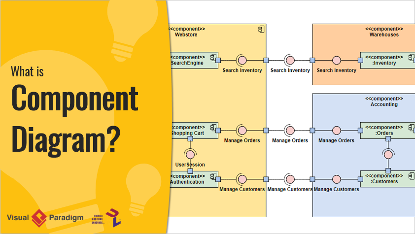
The hierarchy of a Component diagram is akin to a class diagram but with a focus on system components. These components can represent the entire system, subsystems, or specific modules. The hierarchy is visually represented by enclosing components within a bounding box, delineating their scope and relationships.
In a Component diagram, each component operates with a clear objective within the system, interacting only with essential elements as needed. The internal structure of a component is illustrated by its interfaces, both required and provided. Required interfaces denote the services a component relies on, while provided interfaces showcase the services it offers to other components.
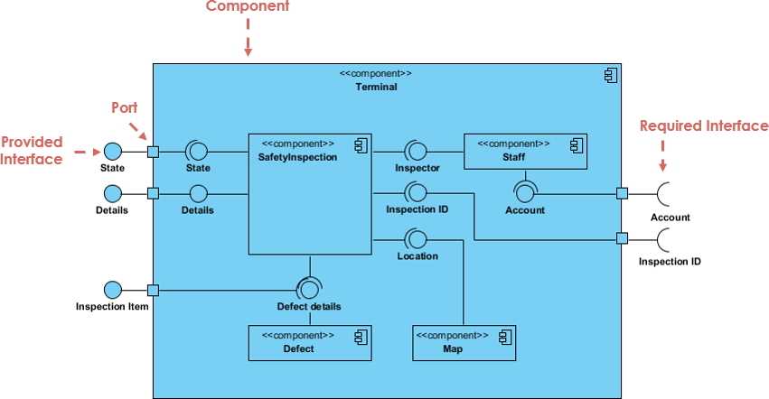
A component is depicted as a rectangle, optionally stacked with compartments. The visual representation includes the component’s name, icon, and stereotype text/icon.
Interfaces play a crucial role in component communication. Provided interfaces, symbolized by a complete circle, represent services offered by the component. On the other hand, required interfaces, depicted with a half circle, signify services a component depends on.
Subsystems are specialized versions of components, identified by the keyword “subsystem” instead of “component.”
Ports, represented by squares along the component’s edge, expose required and provided interfaces. They facilitate the understanding of a component’s interactions.
Component diagrams encompass various relationships, including association, composition, aggregation, constraint, dependency, and generalization. Each relationship type has a specific notation, contributing to a comprehensive system representation.
For source code modeling, components are stereotyped as files. Dependencies among these files are visualized, and tools aid in managing information like version numbers and authors.
Identifying components for an executable release involves considering stereotypes, relationships, and interfaces. This modeling approach helps visualize the system’s structure at the deployment level.
In the context of databases, Component diagrams can represent logical database schemas. Classes representing tables are stereotyped as components, and the diagram reflects the physical distribution of data.
Unified Modeling Language (UML) provides a versatile set of diagrams to model various aspects of software systems. Among these, Component Diagrams, Deployment Diagrams, and Class Diagrams stand out as crucial tools for system architects, developers, administrators, and designers. Each diagram serves a specific purpose, offering a unique perspective on different facets of a system’s structure and behavior.
Here’s a summarized comparison of Component Diagrams, Deployment Diagrams, and Class Diagrams in a tabular format:
| Aspect | Component Diagrams | Deployment Diagrams | Class Diagrams |
|---|---|---|---|
| Purpose | Visualizing, specifying, and documenting component-based systems. | Illustrating the deployment of software components on hardware nodes. | Capturing the static structure of a system in terms of classes and their relationships. |
| Focus | Physical aspects of the system and organization of components. | Physical deployment of software on hardware nodes. | Static structure of the system in terms of classes. |
| Primary Elements | Components, interfaces, and relationships. | Nodes, components, and communication paths. | Classes, associations, and attributes. |
| Abstraction Level | Emphasizes the physical implementation view. | Concentrates on deployment and resource allocation. | Captures the static structure of the system. |
| Context | System architects and developers. | System administrators and IT professionals. | Software developers and designers. |
| Notation | Rectangles for components, interfaces, and relationships. | Nodes, components, and communication paths. | Classes, associations, and attributes. |
Understanding the distinct purposes and focuses of these UML diagrams allows for a comprehensive representation of a system’s architecture, from its physical deployment to its static structure.
In essence, Component Diagrams, Deployment Diagrams, and Class Diagrams serve distinct purposes in UML, offering comprehensive views of different aspects of a system. Integrating these diagrams provides a holistic understanding of a system’s architecture, from its static structure to its physical deployment.
Component Diagrams offer insights into the physical organization of components, Deployment Diagrams focus on the deployment of software on hardware nodes, and Class Diagrams provide a static view of a system’s structure. By understanding the unique contributions of each diagram, stakeholders can holistically model and comprehend diverse aspects of a software system, from its high-level architecture to its physical deployment and static composition. Integrating these perspectives contributes to a comprehensive understanding of complex systems in software development and engineering.
UML Component diagrams offer a powerful means to comprehend the static implementation view of complex systems. By providing a visual roadmap of components and their interactions, these diagrams become indispensable tools for developers, architects, and system analysts alike.
To apply these concepts, consider using Visual Paradigm Community Edition, a free and intuitive UML software. Create your own Component Diagram to enhance your understanding and skills in system modeling.